Power Flow: Voltage Setpoint Tolerance
This is a subtopic of the Power Flow Solution Theory Help.
The ability to use a Voltage Setpoint Tolerance was added in Simulator Version 21
Engineers in charge of operating the entire power transmission system have a voltage schedule that they ask a generator to meet. However, that voltage schedule is not a hard target. Frequently the generator operator is instructed to keep the voltage within a specified tolerance of the given voltage setpoint. Thus the instructions given to a generator at to keep the generator between the Minimum and Maximum Mvar outputs of the generator and also to keep a particular voltage within a tolerance of a setpoint. In additional, this tolerance is often in the range of 0.5 - 2.0 % of nominal voltage. That translates to a tolerance of 0.005 to 0.02 per unit voltage which in the context of a power flow solution can actually be quite large.
This is 4 input parameters: MvarMax, MvarMin, VoltSet, and VoltSetTol. As an example consider the following
- MvarMax = +500
- MvarMin = - 400
- VoltSet = 1.000
- VoltSetTol = 0.010
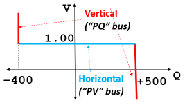
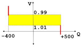
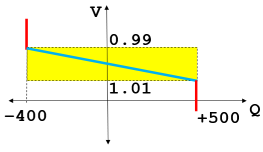
In traditional power flow algorithm discussions and textbooks, the topic of a PQ and PV bus are introduced as shown in the far left figure below. The assumption is that the generator Mvar output will move to any value between the MvarMin and MvarMax value to achieve the voltage setpoint specified. Thus the generator will operated either at on of the Mvar limits on the red lines or on the voltage setpoint represented by the blue line. However, as we just discussed this is not really what a generator is asked to do in real life. Instead the generator is asked to keep the system voltage within a tolerance of the setpoint. Thus what a generator is actually instructed to do is "Stay inside the Yellow Box" in the middle image below. PowerWorld Simulator provides you the ability to specify a voltage setpoint tolerance with each generator (VoltSetTol) and when this is done the solution will follow the blue line in the far right image instead. This means that as the voltage at the regulated bus increases then the reactive power output is going to decrease. Similarly as the voltage at the regulated voltage decreases, then the output of the generator increases. It is important that this equation have this negative dV/dQ relationship to maintain the numerical stability of the power flow solution when using this. We could really use any function between these points, but it makes most sense and is simplest to move along the line from (MvarMax, VoltSet - VoltSetTol) to the point (MvarMin, VoltSet + VoltSetTol).
|
|
|
|
|
When generators change the VoltSetTol to a non-zero value then Powerworld automatically changes the voltage equation enforced for either a locally regulating bus or the primary bus of a group of remotely regulating buses. The BusCat string that you will see in these situation are.
- PVTol: Same as the PV, except the voltage equation for the bus is modified such that when the bus voltage is equal to (VoltSet - VoltSetTol), the generators at the bus will operate at their maximum Mvar Limit and when the bus voltage is equal to (VoltSet + VoltSetTol), the generators at the bus will operate at their minmum Mvar Limit
- PVTol (Remote Reg Primary): Same as the PV (Remote Reg Primary), except the voltage equation for the remote bus is modified such that when the regulated bus voltage is equal to (VoltSet - VoltSetTol), the generators participating in remote regulation will operate at their maximum Mvar Limit and when the regulated bus voltage is equal to (VoltSet + VoltSetTol), the generators participating in remote regulation will operate at their minmum Mvar Limit
- PVTol (Local/Remote Reg Primary): Same concept as PVl (Local/Remote Reg Primary), except this the voltage equation includes the Voltage Setpoint Tolerance again.